The KUMA-1 and KUMA-n type flanged end seals are designed for sealing installation passages through building partitions (single or multi-pipe passages). They are used in non-pressure conditions (up to 2 meters of water column height) and protect against migration of water, mud and gas along the pipeline.
The tightness between the seal and the pipe(s) is ensured by clamping a stainless steel or steel-plastic band.
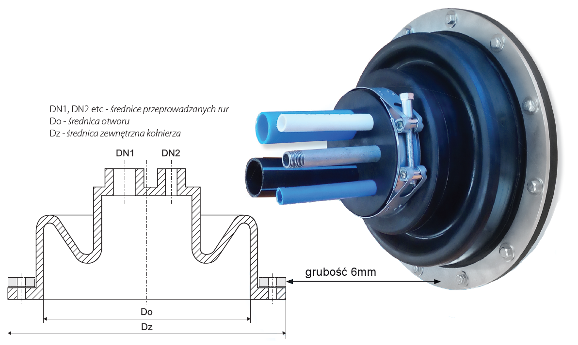
The tightness between the seal flange and partition is obtained by tightening the seal with a steel or plastic flange using screws (expansion pins). The flanges can be one-piece or segmented.
KUMA-1 Flanged end seal (SINGLE-PIPE)

The KUMA-1 can be delivered with plastic flanges (one-piece or segmented).
| KUMA-1 selection chart | ||||
|---|---|---|---|---|
| Diameter of sealed pipe DN [mm] |
Diameter of the hole in the partition Do [mm] | Outer diameter of flange Dz [mm] | Screw diameter Ø [mm] |
Number of screw [psc.] |
| 20-28 | 50 | 110 | 6 | 4 |
| 29-35 | 60 | 120 | 6 | 4 |
| 38-44 | 110 | 180 | 6 | 6 |
| 48-55 | 110 | 180 | 6 | 6 |
| 60-68 | 110 | 180 | 6 | 6 |
| 70-78 | 155 | 245 | 8 | 6 |
| 85-95 | 155 | 245 | 8 | 8 |
| 85-95 | 220 | 300 | 8 | 6 |
| 105-115 | 155 | 245 | 8 | 6 |
| 105-115 | 220 | 300 | 8 | 8 |
| 120-135 | 220 | 300 | 8 | 8 |
| 155-170 | 220 | 300 | 8 | 8 |
| 155-170 | 322 | 408 | 8 | 12 |
| 175-190 | 322 | 350 | 8 | 12 |
| 190-210 | 270 | 350 | 8 | 12 |
| 190-210 | 322 | 408 | 8 | 12 |
| 215-230 | 322 | 408 | 8 | 12 |
| 245-260 | 350 | 445 | 8 | 12 |
| 265-280 | 350 | 445 | 8 | 12 |
| 310-330 | 400 | 508 | 8 | 16 |
| 390-410 | 500 | 600 | 8 | 16 |
| Further diameter ranges available on request | ||||
KUMA-N Flanged end seal (MULTI-PIPE)
Application parameters are the same as for KUMA-1.
The KUMA-n can be delivered with plastic flanges (one-piece or segmented).
| KUMA-n selection chart | |||||
|---|---|---|---|---|---|
| DN | Σ F(DN) [F(DN1) +F(DN2) +...] [mm 2 ] | Do (max) [mm] | Dz [mm] | Screw diameter Ø [mm] | Number of screws [psc.] |
| 25 | 0-120 | 50 | 110 | 6 | 4 |
| 32 | 0-270 | 60 | 120 | 6 | 4 |
| 40 | 0-450 | 110 | 180 | 6 | 6 |
| 50 | 0-720 | 110 | 180 | 6 | 6 |
| 63 | 0-1120 | 110 | 180 | 6 | 6 |
| 75 | 0-1540 | 155 | 245 | 8 | 6 |
| 80 | 0-2270 | 155 | 245 | 8 | 8 |
| 80 | 0-2270 | 220 | 300 | 8 | 6 |
| 100 | 0-3400 | 155 | 245 | 8 | 6 |
| 100 | 0-3400 | 220 | 300 | 8 | 8 |
| 125 | 0-4500 | 220 | 300 | 8 | 8 |
| 150 | 0-7500 | 220 | 300 | 8 | 8 |
| 150 | 0-7500 | 322 | 408 | 8 | 12 |
| 180 | 0-9600 | 270 | 350 | 8 | 12 |
| 200 | 0-11300 | 270 | 350 | 8 | 12 |
| 200 | 0-11300 | 322 | 408 | 8 | 12 |
| 225 | 0-14500 | 320 | 408 | 8 | 12 |
| 250X | 0-18800 | 350 | 445 | 8 | 12 |
| 250 | 0-22000 | 350 | 445 | 8 | 12 |
| 300 | 0-30000 | 400 | 508 | 8 | 16 |
| 400 | 0-48000 | 500 | 600 | 8 | 16 |
|
Σ F(DN) – sum of cross-sections of the pipes [mm2] Further diameter ranges available upon request |
|||||