
In order to properly select casing spacers for your needs, please download, fill in and send the form below to us at the following address: . Thank you.
Choose DOC version
Choose PDF version
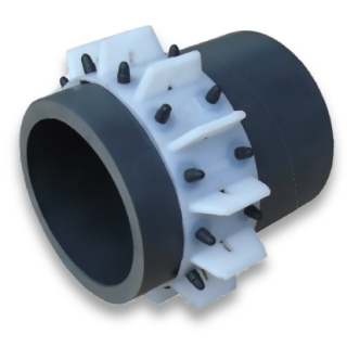
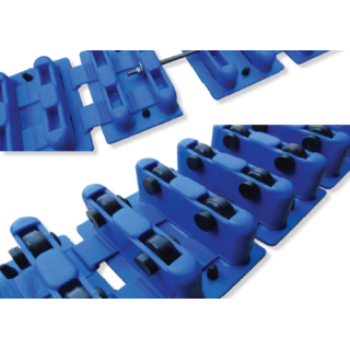
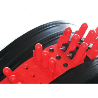
Casing spacers - type a-60 |
Photo of casing spacer type a-60 with pads preventing the spacer from sliding when installed on the pipe:
|
Parameters: |
|
| Available heights (mm): | 15 ; 25 |
| Width (mm): | 60 |
| Lenght (mm): | 485 |
| Diameter range (mm): | 32 - 163 |
| Max static load (kg): | 120 |
| Made of: | MDPE LDPE |
| Permissible temperatures (oC): | -50 do +60 |
| Fastening: | stainless steel M5 screw |
| Number of supports per one element | 13 |
| a-60 spacers selection chart | |
|---|---|
| Diameter range [mm] | Number of supports per one ring |
| ø 32 ÷ 46 | 4 |
| ø 47 ÷ 59 | 5 |
| ø 60 ÷ 70 | 6 |
| ø 71 ÷ 81 | 7 |
| ø 82 ÷ 94 | 8 |
| ø 95 ÷ 105 | 9 |
| ø 106 ÷ 116 | 10 |
| ø 117 ÷ 129 | 11 |
| ø 130 ÷ 141 | 12 |
| ø 142 ÷ 152 | 13 |
| ø 153 ÷ 163 | 14 |
| Spacers for further diameter ranges available on request. |
|
We deliver the a-60 spacers as a ready-to-install rings adapted to the circumference of the pipe or as single elements for self-assembly.
INSTALLATION: a-60 spacers can be supplied as a single-element or multi-element version. Fasten the spacers around the pipe using stainless steel or zinc-coated screws or plastic elements. A multi-element spacer can be obtained via thermal welding of single-elements.
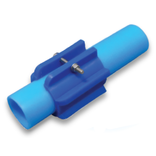
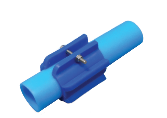
Casing spacers - type a-60 CLIP |
|
Parameters: |
|
| Available heights (mm): | 15 ; 20 ; 25 ; 30 ; 40 |
| Width (mm): | 70 |
| Diameter range (mm): | 20 - 125 |
| Max static load (kg): | 120 |
| Made of: | MDPE LDPE |
| Permissible temperatures (oC): | -50 do +60 |
| Fastening: | stainless steel M5 screw |
| Number of supports per one element | 6 |
| a-60 CLIP spacers selection chart | ||
|---|---|---|
| Diameter range [mm] | Available heights [mm] | Number of supports per one ring |
| 20 | 15 ; 25 | 1 klips |
| 25 | 15 ; 25 | 1 klips |
| 32 | 15 ; 25 | 1 klips |
| 40 | 15 ; 25 | 1 klips |
| 50 | 15 ; 20 | 1 klips |
| 63 | 15 ; 30 | 1 klips |
| 75 | 15 ; 25 | 1 klips |
| 90 | 15 ; 25 | 1 klips |
| 110 | 15 ; 25 ; 40 | 1 klips |
| 125 | 15 ; 25 ; 40 | 1 klips |
| Spacers for further diameter ranges available on request. |
||
INSTALLATION: Fasten the spacers around the pipe using stainless steel or zinc-coated screws or plastic elements.
Casing spacers - type a-120 |
|
Parameters: |
|
| Available heights (mm): | 25 ; 40 ; 60 |
| Width (mm): | 120 |
| Diameter range (mm): | 105 - 347 |
| Max static load (kg): | 250 |
| Made of: | MDPE LDPE |
| Permissible temperatures (oC): | -50 do +60 |
| Fastening: | stainless steel M5 screws |
| Number of supports per one element: | 12 |
| a-120 spacers selection chart | |
|---|---|
| Diameter range [mm] | Number of supports per one ring |
| ø 105 ÷ 121 | 7 |
| ø 122 ÷ 139 | 8 |
| ø 140 ÷ 156 | 9 |
| ø 157 ÷ 172 | 10 |
| ø 173 ÷ 189 | 11 |
| ø 190 ÷ 207 | 12T |
| ø 208 ÷ 224 | 13 |
| ø 225 ÷ 244 | 14 |
| ø 245 ÷ 251 | 15 |
| ø 262 ÷ 278 | 16 |
| ø 279 ÷ 295 | 17 |
| ø 296 ÷ 312 | 18 |
| ø 313 ÷ 330 | 19 |
| ø 331 ÷ 347 | 20 |
| Spacers for further diameter ranges available on request. |
|
INSTALLATION: a-120 spacers can be supplied as a single-element or multi-element version. Fasten the spacers around the pipe using stainless steel or zinc-coated screws or plastic elements. A multi-element spacer can be obtained via thermal welding of single-elements or by joining them using screws.
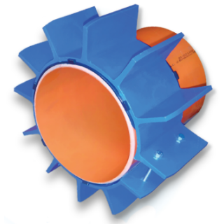
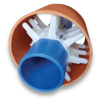
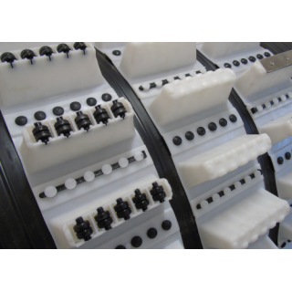
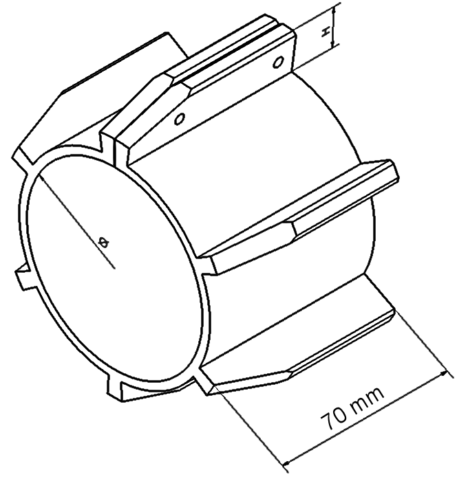
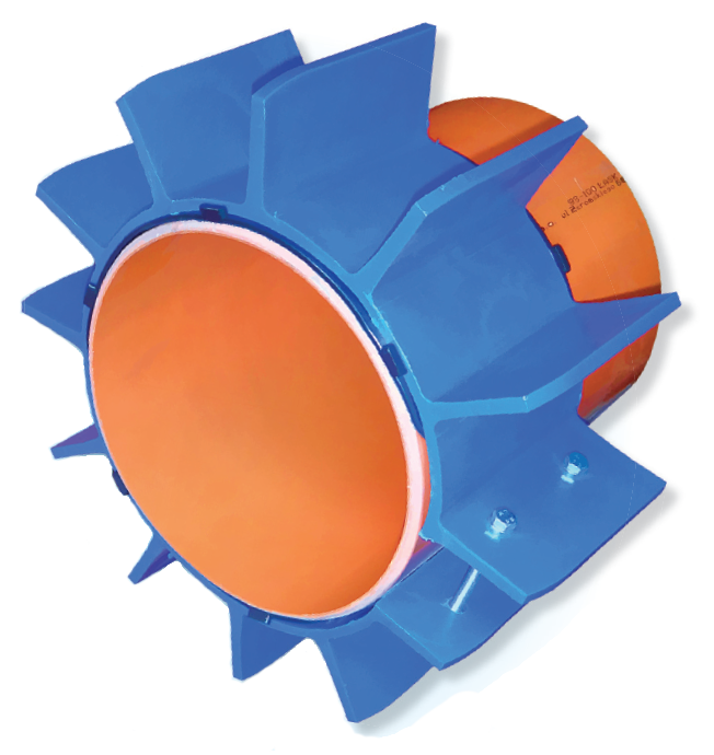
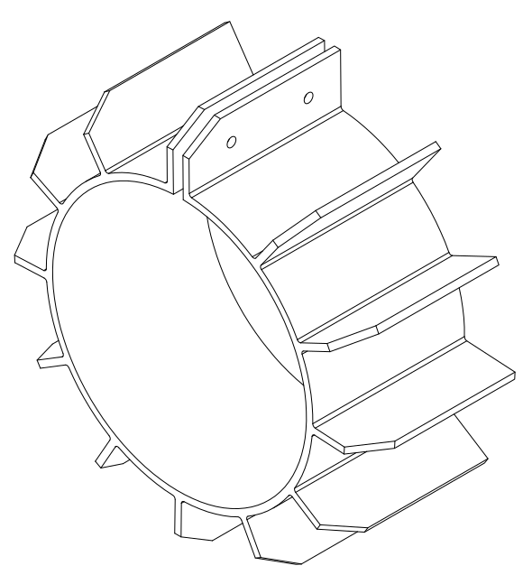
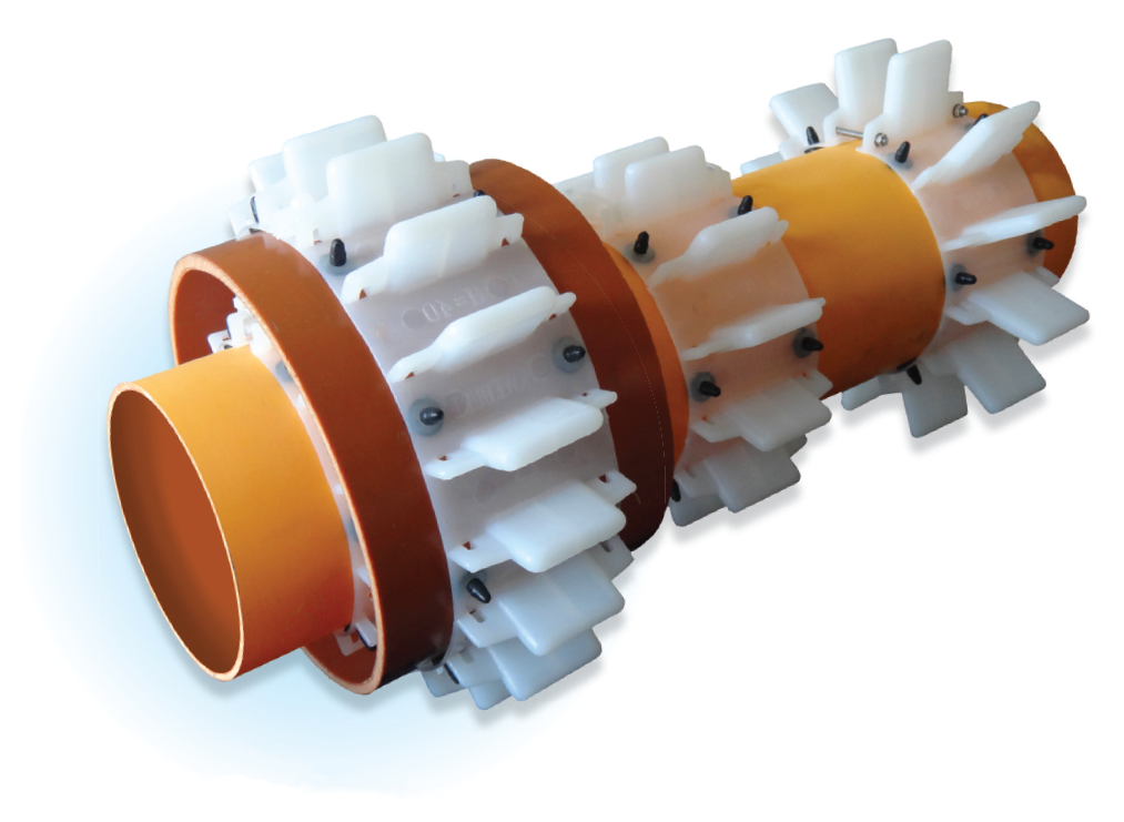
Casing spacers - type a-NT |
Photo of casing spacers type a-NT with elastomer pads preventing the spacer from sliding when installed on the pipe:

|
Parameters: |
|
| Available heights (mm): | 15 ; 25 ; 40 ; 60 ; 80 ; 100 |
| Width (mm): | 100 |
| Lenght (mm): | 550 |
| Diameter range (mm): | 75 - 418 |
| Max static load (kg): | 300 |
| Made of: | MDPE |
| Permissible temperatures (oC): | -50 do +60 |
| Fastening: | stainless steel M5 screws |
| Number of supports per one element: | 12 |
| a-NT spacers selection chart | |
|---|---|
| Diameter range [mm] | Number of supports per one ring |
| ø 75 ÷ 88 | 6 |
| ø 89 ÷ 101 | 7 |
| ø 102 ÷ 116 | 8 |
| ø 117 ÷ 130 | 9 |
| ø 131 ÷ 144 | 10 |
| ø 145 ÷ 157 | 11 |
| ø 158 ÷ 168 | 12 |
| ø 169 ÷ 183 | 13 |
| ø 184 ÷ 197 | 14 |
| ø 198 ÷ 207 | 15 |
| ø 208 ÷ 225 | 16 |
| ø 226 ÷ 233 | 17 |
| ø 234 ÷ 253 | 18 |
| ø 254 ÷ 268 | 19 |
| ø 269 ÷ 280 | 20 |
| ø 281 ÷ 294 | 21 |
| ø 295 ÷ 308 | 22 |
| ø 309 ÷ 320 | 23 |
| ø 321 ÷ 334 | 24 |
| ø 335 ÷ 348 | 25 |
| ø 349 ÷ 362 | 26 |
| ø 363 ÷ 376 | 27 |
| ø 377 ÷ 390 | 28 |
| ø 391 ÷ 405 | 29 |
| ø 406 ÷ 418 | 30 |
| Spacers for further diameter ranges available on request. |
|
We deliver the a-NT spacers as a ready-to-install rings adapted to the circumference of the pipe or as single elements for self-assembly.
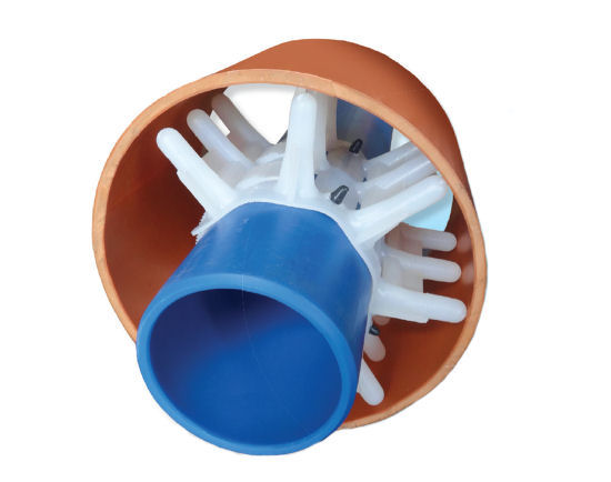
A single a-NT-type spacer element consists of 12 supports and is suitable for installation on a ø160 carrier pipe. In order to obtain the correct ring length of spacers for other diameters, we join and/or cut out the appropriate number of supports, in accordance with information provided in the a-NT-type spacer selection table.
ASSEMBLY: assembling the spacers of a-NT system consists in tightening the ring on the pipe by means of fasteners (steel or
plastic). The multi-element version is made by connecting several basic elements.
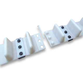
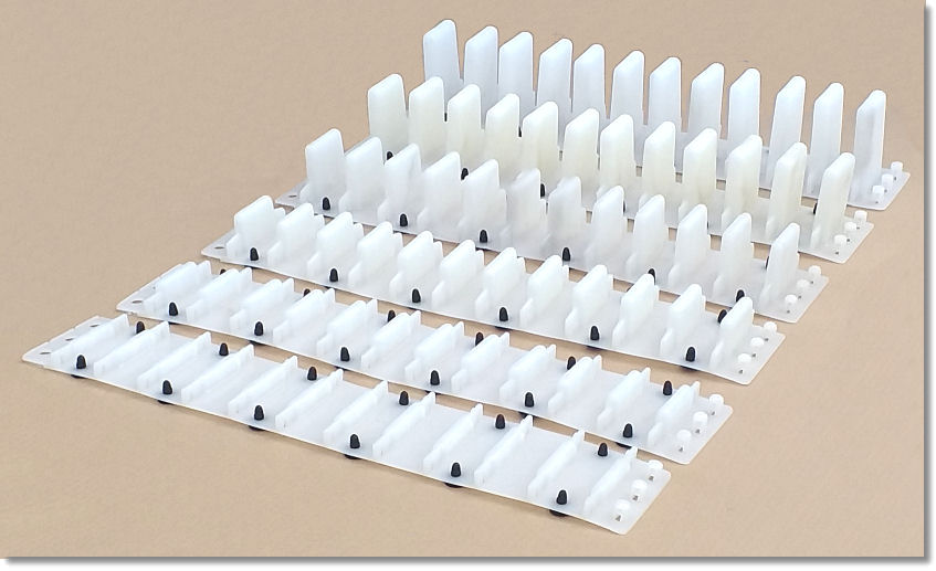
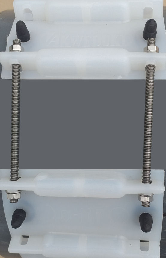
Method of joining of single NT-type spacer elements:
The installation of a-NT spacers comprises of the tightening of ring on a pipe using two M5 bolts.
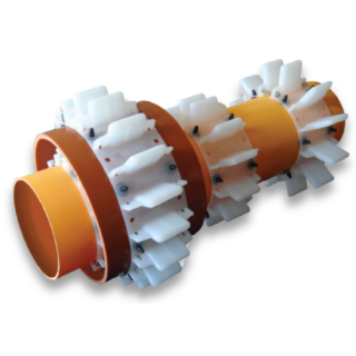
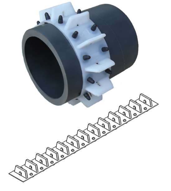
Casing spacers - type A-NT |
Photo of casing spacers type A-NT with elastomer pads preventing the spacer from sliding when installed on the pipe:
|
Parameters: |
|
| Available heights (mm): | 12 ; 15 ; 25 ; 30 ; 45 ; 60 ; 80 |
| Width (mm): | 125 |
| Lenght (mm): | 170 |
| Diameter range (mm): | 94 - 660 |
| Max static load (kg): | 500 |
| Made of: | MDPE LDPE |
| Permissible temperatures (oC): | -50 do +60 |
| Fastening: | toothed belts + stainless steel M6 screws |
| Number of supports per one element: | 2 |
| A-NT spacers selection chart | |
|---|---|
| Diameter range [mm] | Number of supports per one ring |
| ø 94 ÷ 109 | 6 |
| ø 110 ÷ 124 | 7 |
| ø 125 ÷ 140 | 8 |
| ø 141 ÷ 158 | 9 |
| ø 159 ÷ 186 | 10 |
| ø 187 ÷ 217 | 12 |
| ø 218 ÷ 248 | 14 |
| ø 249 ÷ 284 | 16 |
| ø 285 ÷ 315 | 18 |
| ø 316 ÷ 350 | 20 |
| ø 351 ÷ 375 | 22 |
| ø 376 ÷ 405 | 24 |
| ø 406 ÷ 437 | 26 |
| ø 438 ÷ 469 | 28 |
| ø 470 ÷ 505 | 30 |
| ø 506 ÷ 540 | 32 |
| ø 541 ÷ 569 | 34 |
| ø 570 ÷ 599 | 36 |
| ø 600 ÷ 629 | 38 |
| ø 630 ÷ 660 | 40 |
| Spacers for further diameter ranges available on request. |
|
Rollers which facilitate introduction into the casing pipe are available with the following heights: 30 mm; 45 mm; 60 mm; 80 mm
We deliver the A-NT spacers as a ready-to-install rings adapted to the circumference of the pipe or as single elements for self-assembly.
INSTALLATION: the installation of type A-NT spacers entails the introduction of a toothed belt into the seat in the second spacer. By connecting an adequate number of single elements, we can obtain a ring of spacers suitable for the specific carrier pipe diameter. The ring can be tightened using an M6 bolt.
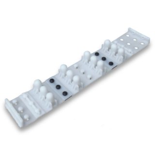
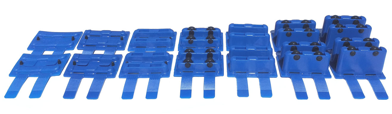
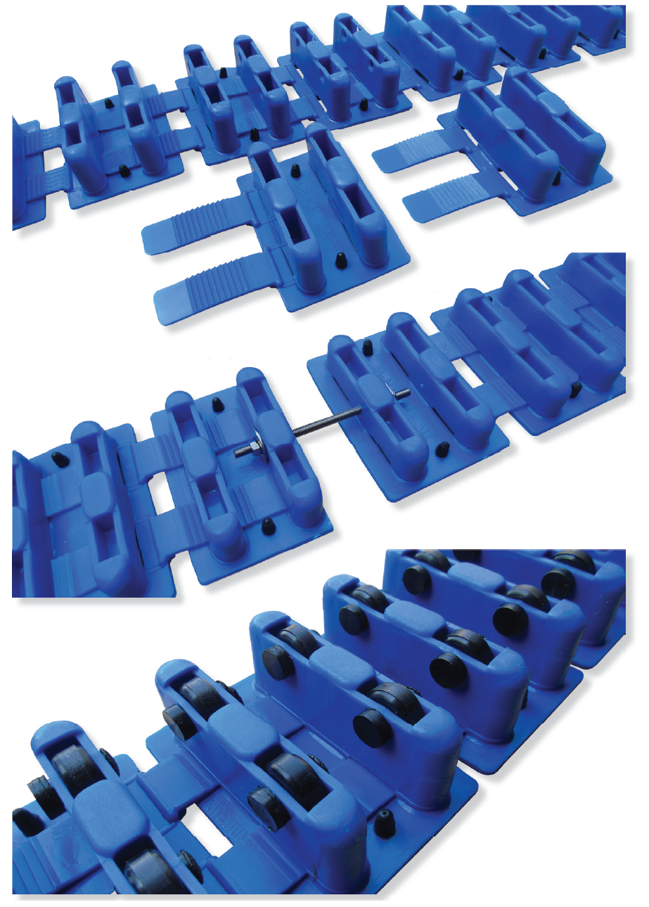
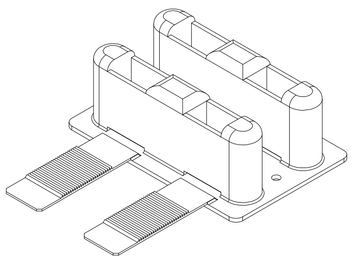
Casing spacers - type A and Ad |
Photo of casing spacer type Ad with elastomer pads preventing the spacer from sliding when installed on the pipe:
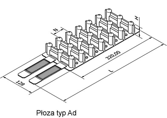
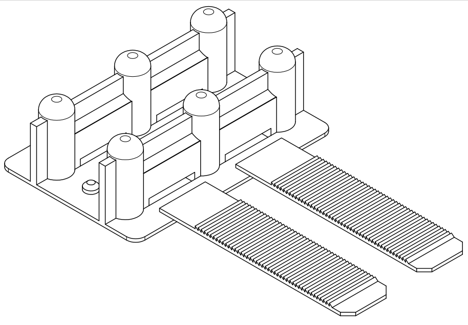
Płoza A
|
Parameters: |
|
| Available heights (mm): | 15 ; 25 ; 42 ; 61 ; 80 |
| Width (mm): | 128 |
| A lenght (mm): | 205 |
| Ad lenght (mm): | 435 |
| Diameter range (mm): | 90 - 410 |
| Max static load (kg): | 200 |
| Made of: | MDPE LDPE |
| Permissible temperatures (oC): | -50 do +60 |
| Fastening: | |
| Number of supports per one element: A/Ad | 2/7 |
| A spacers selection chart | |
|---|---|
| Diameter range [mm] | Number of supports per one ring |
| ø 90 ÷ 105 | 6 |
| ø 106 ÷ 122 | 7 |
| ø 123 ÷ 135 | 8 |
| ø 136 ÷ 151 | 9 |
| ø 152 ÷ 165 | 10 |
| ø 166 ÷ 181 | 11 |
| ø 182 ÷ 196 | 12 |
| ø 197 ÷ 211 | 13 |
| ø 212 ÷ 226 | 14 |
| ø 227 ÷ 241 | 15 |
| ø 242 ÷ 256 | 16 |
| ø 257 ÷ 271 | 17 |
| ø 272 ÷ 286 | 18 |
| ø 287 ÷ 302 | 19 |
| ø 303 ÷ 317 | 20 |
| ø 318 ÷ 332 | 21 |
| ø 333 ÷ 347 | 22 |
| ø 348 ÷ 363 | 23 |
| ø 364 ÷ 378 | 24 |
| ø 379 ÷ 393 | 25 |
| ø 394 ÷ 410 | 26 |
| Spacers for further diameter ranges available on request. |
|
We deliver the A and Ad spacers as a ready-to-install rings adapted to the circumference of the pipe or as single elements for self-assembly.
INSTALLATION: the installation of A and Ad type spacers entails the introduction of toothed belts of the first spacer into the seats of the last spacer and their firm tightening. The A spacers can be joined with Ad.
Casing spacers - type BC |
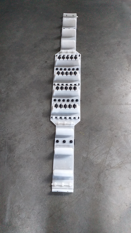
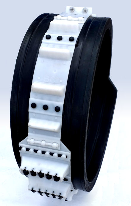
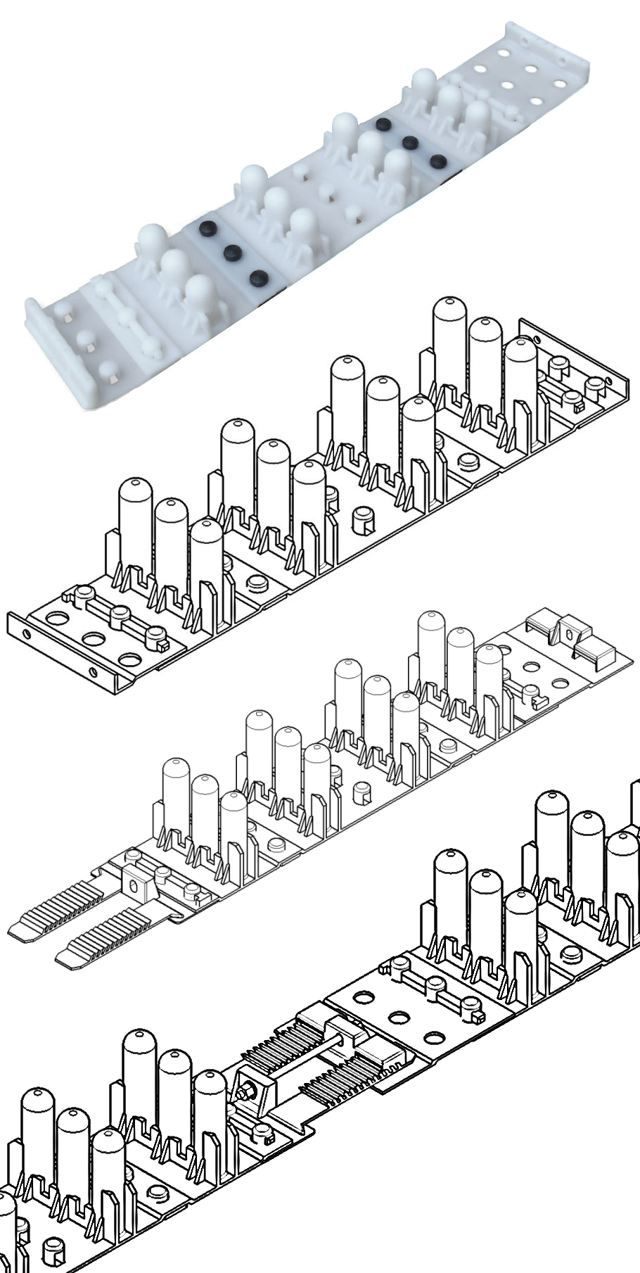
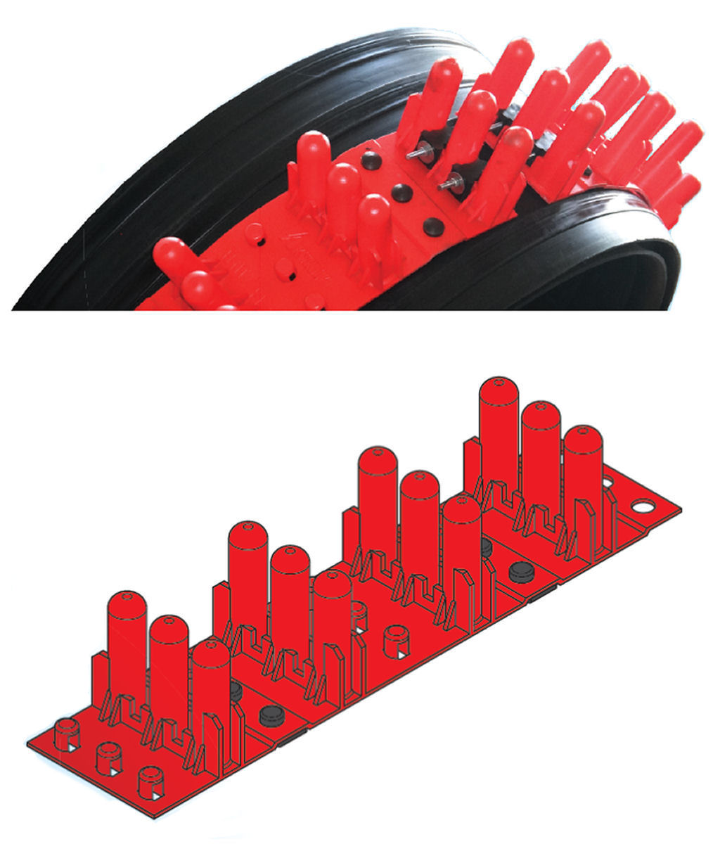
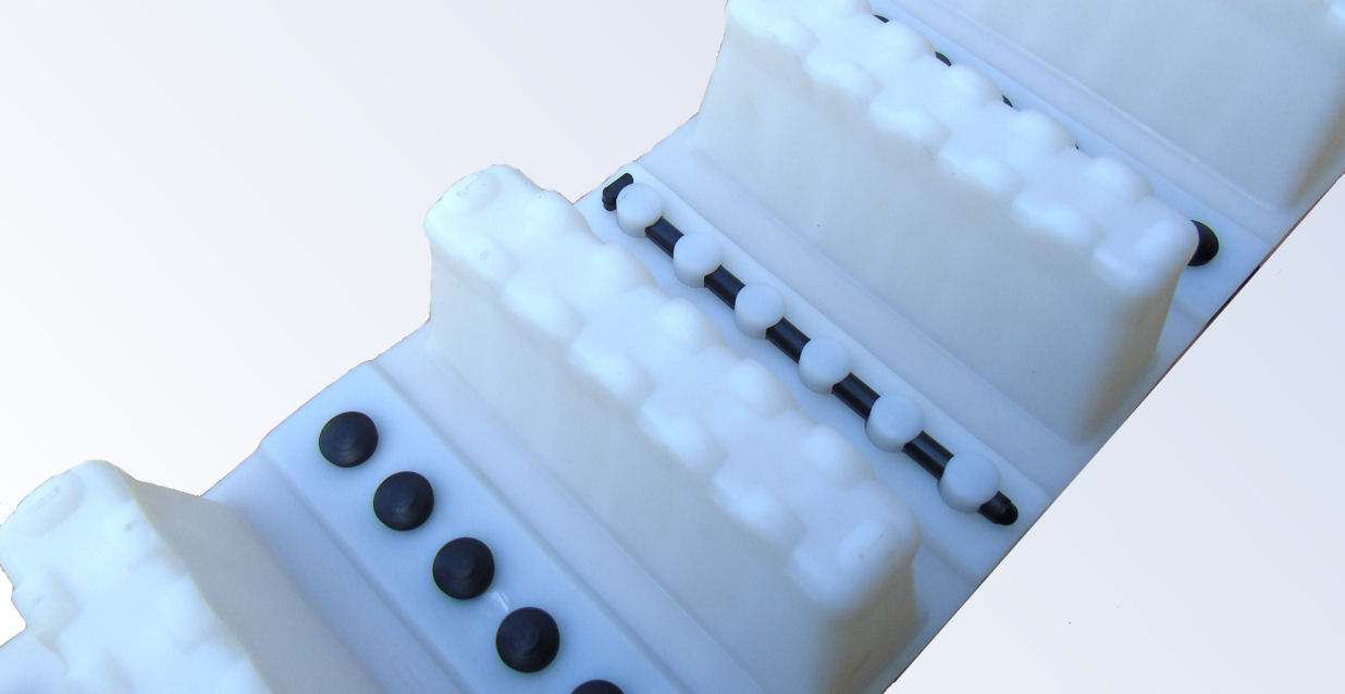
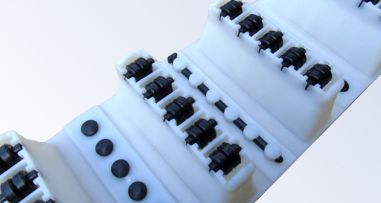
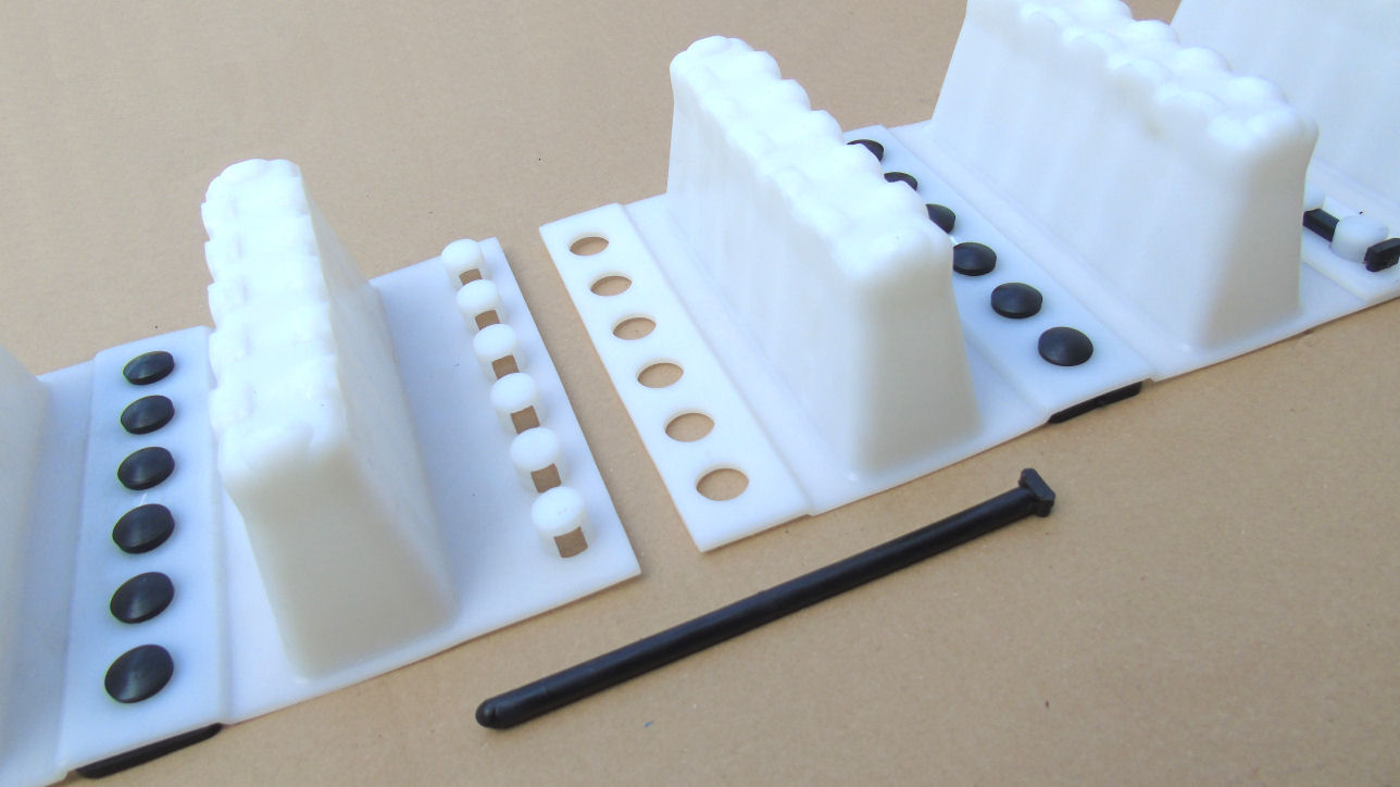
Photo of casing spacer type BC with elastomer pads preventing the spacer from sliding when installed on the pipe:
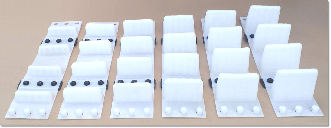
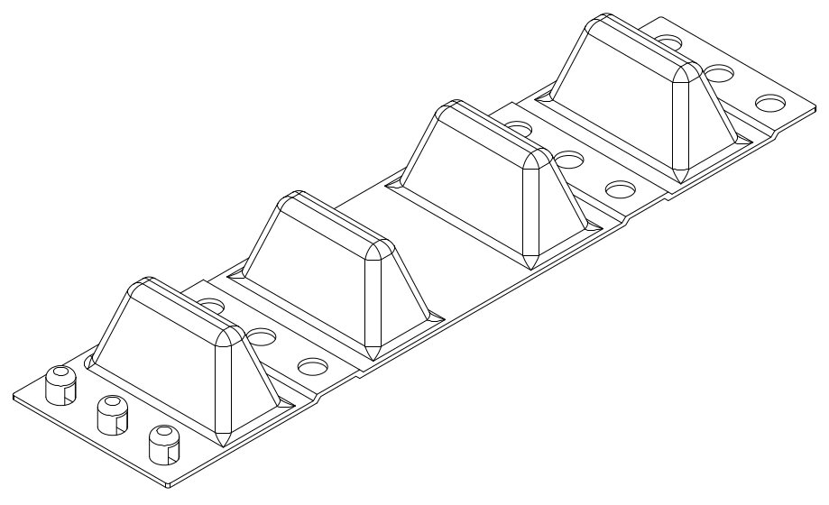
A single BC spacer consists of 4 supports. In order to obtain an adequate number of supports to the diameter/circumference of the pipe, we join spacers together using a peg and/or trim (cut short) the spacer by one or two supports.
|
Parameters: |
|
| Available heights (mm): | 35 ; 50 ; 65 ; 80 ; 95 ; 110 |
| Width (mm): | 135 |
| Lenght (mm): | 600 |
| Diameter range (mm): | 225 - 1388 |
| Max static load (kg): | H>80-1500kg H≤80-1800kg |
| Made of: | HDPE |
| Permissible temperatures (oC): | -50 do +70 |
| Fastening: | stainless steel M8 screws |
| Number of supports per one element: | 4 |
| BC spacers selection chart | |
|---|---|
| Diameter range [mm] | Number of supports per one ring |
| ø 225 ÷ 308 | 4 |
| ø 309 ÷ 352 | 6 |
| ø 353 ÷ 397 | 7 |
| ø 398 ÷ 443 | 8 |
| ø 444 ÷ 487 | 9 |
| ø 488 ÷ 532 | 10 |
| ø 533 ÷ 577 | 11 |
| ø 578 ÷ 624 | 12 |
| ø 625 ÷ 668 | 14 |
| ø 669 ÷ 713 | 14 |
| ø 714 ÷ 757 | 15 |
| ø 758 ÷ 803 | 16 |
| ø 804 ÷ 848 | 16 |
| ø 849 ÷ 893 | 16 |
| ø 894 ÷ 937 | 18 |
| ø 938 ÷ 983 | 19 |
| ø 984 ÷ 1028 | 20 |
| ø 1029 ÷ 1072 | 21 |
| ø 1073 ÷ 1117 | 22 |
| ø 1118 ÷ 1163 | 23 |
| ø 1164 ÷ 1208 | 23 |
| ø 1209 ÷ 1252 | 26 |
| ø 1253 ÷ 1297 | 26 |
| ø 1298 ÷ 1343 | 27 |
| ø 1344 ÷ 1388 | 28 |
| Spacers for further diameter ranges available on request. |
|
We deliver the BC spacers as a ready-to-install rings adapted to the circumference of the pipe or as single elements for self-assembly.
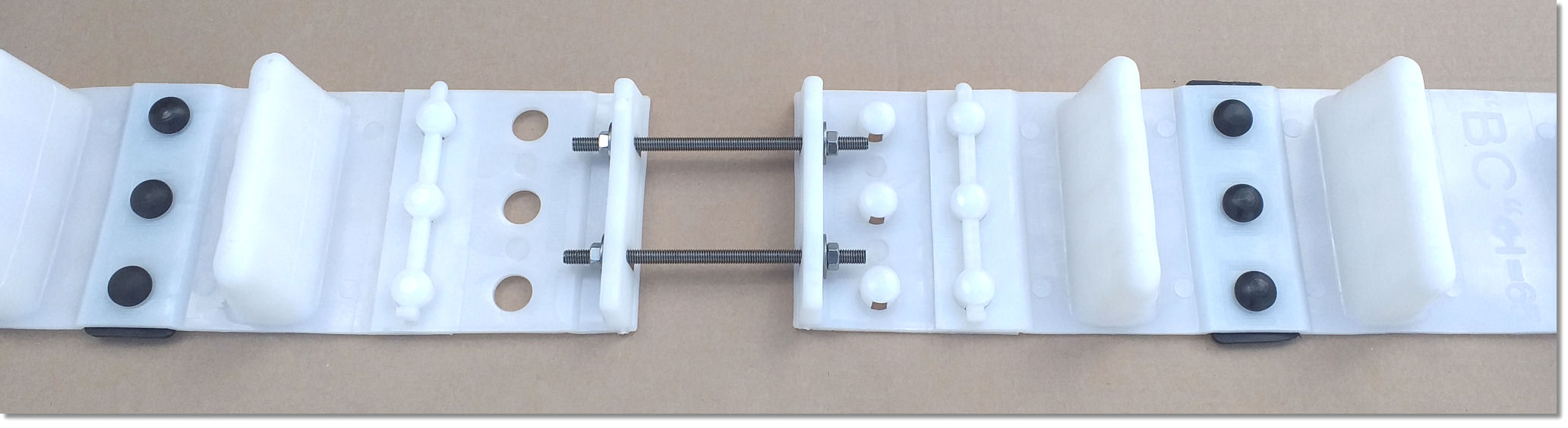
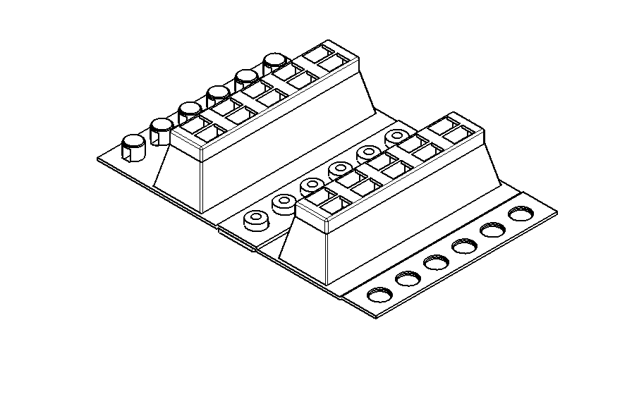
INSTALLATION: In order to obtain a spacer ring suitable for a specific diameter of carrier pipe, we join together an adequate number od main elements using a peg.
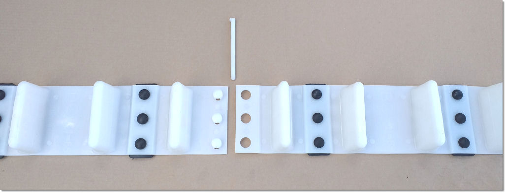
The finished ring is then tightened on the pipe using two M8 bolts.
Casing spacers - type B-NT |
Photo of casing spacer type B-NT with elastomer pads preventing the spacer from sliding when installed on the pipe:
|
Parameters: |
|
| Available heights (mm): | 35 ; 65 ; 85 ; 60 ; 115 |
| Width (mm): | 148 |
| Lenght (mm): | 600 |
| Diameter range (mm): | 285 - 1700 |
| Max static load (kg): | 1500 |
| Made of: | HDPE |
| Permissible temperatures (oC): | -50 do +70 |
| Fastening: | stainless steel M8 screws |
| Number of supports per one element: | 4 |
| Selection chart of B-NT bolted spacers | |
|---|---|
| Diameter range [mm] | Number of supports per one ring |
| ø285-315 | 7 +Z |
| ø330-374 | 8 +Z |
| ø375-419 | 9 +Z |
| ø420-464 | 10 +Z |
| ø465-500 | 11 +Z |
| ø510-554 | 12 +Z |
| ø555-598 | 13 +Z |
| ø599-642 | 14 +Z |
| ø643-687 | 15 +Z |
| ø688-732 | 16 +Z |
| ø733-777 | 17 +Z |
| ø778-822 | 18 +Z |
| ø823-866 | 19 +Z |
| ø867-910 | 20 +Z |
| ø911-955 | 21 +Z |
| ø956-999 | 22 +Z |
| ø1000-1044 | 23 +Z |
| ø1045-1088 | 24 |
| ø1089-1133 | 25 +Z |
| ø1134-1178 | 26 +Z |
| ø1179-1222 | 27 +Z |
| ø1223-1267 | 28 +Z |
| ø1268-1310 | 29 +Z |
| ø1311-1356 | 30 +Z |
| ø1357-1400 | 31 +Z |
| ø1401-1445 | 32 +Z |
| ø1446-1490 | 33 +Z |
| ø1491-1534 | 34 +Z |
| ø1535-1579 | 35 +Z |
| ø1580-1624 | 36 +Z |
| Spacers for further diameter ranges available on request. Z - closure |
|
| Selection chart of B-NT belt-mounted spacers | |
|---|---|
| Diameter range [mm] | Number of supports per one ring |
| ø <400 | 7 +Z |
| ø401-445 | 8 +Z |
| ø446-490 | 9 +Z |
| ø491-534 | 10 +Z |
| ø535-579 | 11 +Z |
| ø580-624 | 12 +Z |
| ø625-667 | 13 +Z |
| ø668-712 | 14 +Z |
| ø713-757 | 15 +Z |
| ø758-802 | 16 +Z |
| ø803-846 | 17 +Z |
| ø847-891 | 18 +Z |
| ø892-936 | 19 +Z |
| ø937-980 | 20 +Z |
| ø981-1025 | 21 +Z |
| ø1026-1069 | 22 +Z |
| ø1070-1114 | 23 +Z |
| ø1115-1159 | 24 +Z |
| ø1160-1204 | 25 +Z |
| ø1205-1248 | 26 +Z |
| ø1249-1290 | 27 +Z |
| ø1291-1335 | 28 +Z |
| ø1336-1381 | 29 +Z |
| ø1382-1425 | 30 +Z |
| ø1426-1469 | 31 +Z |
| ø1470-1514 | 32 +Z |
| ø1515-1559 | 33 +Z |
| ø1560-1604 | 34 +Z |
| ø1605-1649 | 35 +Z |
| ø1650-1700 | 36 +Z |
| Spacers for further diameter ranges available on request. Z - closure |
|
We deliver the B-NT spacers as a ready-to-install rings adapted to the circumference of the pipe or as single elements for self-assembly.
INSTALLATION: In order to obtain a spacer ring suitable for a specific diameter of carrier pipe, we join together an adequate number od main elements using a peg. The finished ring is then tightened on the pipe using two M8 bolts.
In the case of belt mounted spacers, we insert the toothed belt of the first spacer into the seat of the las spacer and tighten using a single M8 bolt. When tightened firmly, the ring is held by the toothed belts and the bolt can be removed.
Casing spacers - type B-NT RED |
|
Parameters: |
|
| Available heights (mm): | 35 ; 65 ; 85 ; 115 |
| Width (mm): | 100 |
| Lenght (mm): | 600 |
| Diameter range (mm): | 285 - 1700 |
| Max static load (kg): | 2000 |
| Made of: | POM |
| Permissible temperatures (oC): | -60 do +90 |
| Fastening: | stainless steel M8 screws |
| Number of spacers per one element: | 4 |
We deliver the B-NT RED spacers as a ready-to-install rings adapted to the circumference of the pipe or as single elements for self-assembly.
INSTALLATION: In order to obtain a spacer ring suitable for a specific diameter of carrier pipe, we join together an adequate number od main elements using a peg. The finished ring is then tightened on the pipe using two M8 bolts.
In the case of belt mounted spacers, we insert the toothed belt of the first spacer into the seat of the las spacer and tighten using a single M8 bolt. When tightened firmly, the ring is held by the toothed belts and the bolt can be removed.
Casing spacers - type C |
Photo of casing spacer type C with elastomer pads preventing the spacer from sliding when installed on the pipe:
|
Parameters: |
|
| Available heights (mm): | 35 ; 65 ; 95 ; 110 ; 140 |
| Width (mm): | 220 |
| Lenght (mm): | 335 |
| Diameter range (mm): | 516 - 1783 |
| Max static load (kg): | 2500 |
| Made of: | HDPE |
| Permissible temperatures (oC): | -50 do +70 |
| Fastening: | stainless steel M8 screws |
| Number of spacers per one element: | 2 |
| C spacers selection chart | |
|---|---|
| Diameter range [mm] | Number of supports per one ring |
| ø 516 ÷ 561 | 6 +Z |
| ø 562 ÷ 608 | 7 +Z |
| ø 609 ÷ 655 | 8 +Z |
| ø 656 ÷ 702 | 9 +Z |
| ø 703 ÷ 749 | 10 +Z |
| ø 750 ÷ 796 | 11 +Z |
| ø 797 ÷ 842 | 12 +Z |
| ø 843 ÷ 890 | 13 +Z |
| ø 891 ÷ 937 | 14 +Z |
| ø 938 ÷ 984 | 15 +Z |
| ø 985 ÷ 1031 | 16 +Z |
| ø 1032 ÷ 1078 | 17 +Z |
| ø 1079 ÷ 1124 | 18 +Z |
| ø 1125 ÷ 1172 | 19 +Z |
| ø 1173 ÷ 1218 | 20 +Z |
| ø 1219 ÷ 1266 | 21 +Z |
| ø 1267 ÷ 1313 | 22 +Z |
| ø 1314 ÷ 1360 | 23 +Z |
| ø 1361 ÷ 1407 | 24 +Z |
| ø 1408 ÷ 1454 | 25 +Z |
| ø 1455 ÷ 1501 | 26 +Z |
| ø 1502 ÷ 1548 | 27 +Z |
| ø 1549 ÷ 1595 | 28 +Z |
| ø 1596 ÷ 1642 | 29 +Z |
| ø 1643 ÷ 1689 | 30 +Z |
| ø 1690 ÷ 1736 | 31 +Z |
| ø 1737 ÷ 1783 | 32 +Z |
| Spacers for further diameter ranges available on request. Z - closure |
|
We deliver the C spacers as a ready-to-install rings adapted to the circumference of the pipe or as single elements for self-assembly.
INSTALLATION: In order to obtain a spacer ring suitable for a specific diameter of carrier pipe, we join together an adequate number od main elements using a peg. The finished ring is then tightened on the pipe using two M8 bolts.